Build Guide Details
This is the multi-page printable view of this section. Click here to print.
Build Guide
Build your own Campfyre
- 1: Introduction
- 2: Components
- 3: Architecture
- 4: Assembly
- 5: Printable Parts
- 5.1: Battery Holder
- 5.2: DCDC-8A Mount
- 5.3: Epic PWRGate Mount
- 5.4: Starlink Mount Corner A
- 5.5: Starlink Mount Corner B
- 5.6: Starlink Mount Half
- 5.7: Voltmeter Mount
1 - Introduction
Learn the basics for how Campfyre works, what you need to know, and the prerequisites for making your own.
Tools
To get started building your own Campfyre, you’ll need the following tools.
- 3D Printer
- Soldering iron
- Power drill
- Wire cutter
- Screwdriver set
- Ring terminal crimp tool
- Lighter/heat source (for heat shrink tubing)
- 120-160 grit sand paper
- Scissors
Consumables
A few consumables will be needed to build Campfyre.
- 12 AWG wire (red and black)
- M3 screws (assorted)
- M3 heat-set inserts
- M4 screws (assorted)
- M4 heat-set inserts
- 3M Low Surface Energy VHB Tape (3M LSE-060WF)
- Ethernet cables
- 5.5x2.5mm DC plug
- M3 and M5 yellow ring terminals for 12 AWG wire
WARNING
Purchasing specifically 3M LSE VHB tape is absolutely essential. No, foam mounting tape will not work. You must purchase exactly this tape for Campfyre to work. It’s possible you will use an entire 15ft roll of 1/2-in tape to build Campfyre.
Components
Components are discussed further on their dedicated page.
Printable Parts
150x65mm Battery Holder
This is a predesigned holder for 150x65mm batteries. These are common LiFePO4 batteries found in uninterruptable power supplies, and can be ordered from the supplier listed in the components page.DCDC-8A Mount
The DCDC-8A Mount is the mount that holds the DCDC-8A in the case, allowing for it to be removed by unscrewing it rather than having it permanently affixed directly into the case.Epic PWRGate Mount
The Epic PWRGate is the power path controller which selects the power source to use for supplying the rest of Campfyre.Starlink Mount Corner A
This is what screws into the Starlink Mount to hold the Starlink Mini in place. Print two of these for Campfyre.Starlink Mount Corner B
This is what screws into the Starlink Mount to hold the Starlink Mini in place. Print two of these for Campfyre.Starlink Mount Half
This is the base that attaches to the case, to which the Starlink is then attached. Print two of these for Campfyre.Voltmeter Mount
This attaches the voltmeter (and associated pushbutton) to the side of the case, so you can check the battery voltage.2 - Components
The basic components that make up Campfyre.
These are the basic components that Campfyre utilizes. Each component will have a brief description of why it was selected, and any specific requirements for choosing a replacement. Note that only the listed components have shown to work, and untested replacements are not guaranteed to operate (or fit) properly.
Google Sheet link to primary component listing.
Notes before starting
Campfyre has been designed to support 15A of load on downstream devices within the case. Starlink takes up to 5A input, and a Raspberry Pi 5 can require up to 5A. It is recommended to use the Starlink without snow melt mode. It is also recommended to use a Raspberry Pi 4 Model B, as Pi 5s are power-hungry and output a lot of heat.
Starlink Mini
Campfyre has been designed around the use of a Starlink Mini with a Roam plan. Starlink must be activated with in-motion use enabled (Roam plan), as the goal of Campfyre is to provide internet service without a dedicated location selected.
Make sure you turn off snow melt mode on the Starlink, otherwise it will heat up internally and could cause damage in the sealed environment within the case.
Power Supply & Management
These are the bread and butter of the internal architecture of Campfyre. Each one
12V VBUS Power Supply
This is the main VBUS power supply that connects between the power path controller and the downstream devices, such as the Starlink Mini and the network switch.
The VBUS supply must accept 8-15V DC, and regulate it to an even 12V. This is to smooth out the power from the battery, vehicle alternator/battery, or other sources that may not deliver “clean” power.
Requirements
- 8-15V DC in
- 12V @ 8A+ out
5V Power Supply
This is to provide power to the Raspberry Pi. It should accept 12V DC in, and output 5.1V at 3A or more. Any 5V DC-DC power supply that fits your case should work, but the one selected has been validated to work well.
Requirements
- 12V DC in
- 5.1V @ 3A+ out
Power Path Controller
This is the device that switches between external DC in (VIN) and the battery to power downstream devices. It sits between the battery, VIN, and the primary VBUS supply. It is not an easy part to find replacements for. It must be able to switch between VIN and battery instantaneously, and must be solid-state. Relays are too slow for power to transition smoothly, and could cut out power to Starlink or to the Raspberry Pi.
Requirements
- 8-15V DC in for VIN
- 8-15V DC in for battery
- 8-15V DC out for downstream devices
- Automated cutover between external DC and battery
- Handle at least 8A of current, but recommended to have a safety factor of at least 2
Battery
The battery is one of the most important parts of the device. It must be able to supply at least 8A of current, and be of the same chemistry as the charger supports.
WARNING
Batteries are dangerous. Large capacity ones especially so. For Campfyre to remain safe, you must purchase 12V LiFePO4 batteries. LiPo/Li-Ion batteries are not compatible, and sealed lead-acid (SLA) batteries are also not compatible. Using a LiFePO4 charger with the wrong type of batteries can result in an explosion. Do not charge a LiFePO4 battery at temperatures below freezing.
Requirements
- 8A+ discharge current (ideally >10A)
- 12V (4S) LiFePO4 battery
Battery Charger
The battery charger must accept 8-15V DC in and boost the voltage to standard charging voltages for the battery you’ve chosen. In addition, it should support the chemistry of the battery selected.
DC-DC battery chargers are fairly rare, and so the one selected for Campfyre has already been validated to work with the selected battery and voltage input.
Requirements
- 8-15V DC in
- 12V (4S) LiFePO4 battery support
Protection
Circuit Breakers
The circuit breakers are used to turn on and off the power inside Campfyre, and prevent sudden spikes from causing sparks, fires, or melting wires. The circuit breakers should be rated for 15A, and support switching under load.
Requirements
- 24V+ DC rating
- 15A capacity rating
- B curve or better
- Switch under load
Fuses
25A fuses should be used to protect Campfyre, and placed on both the battery positive lead and VIN positive lead. MIDI fuses are used for ease of installation, and ease of sourcing. It is recommended against using automotive blade fuses.
Requirements
- 24V+ DC rating
- 25A DC rating
External Connectors
Campfyre uses Cnlinko connectors for VIN and the Ethernet jack, due to their waterproofing. Any connector that is capable of handling 15A of current at 12V DC, though, should be usable.
Requirements
- 15A DC rating
- 24V+ DC rating
- 2 or 3 pin for power
- RJ45 for Ethernet
3 - Architecture
See how Campfyre is put together.
Campfyre is designed around a few key subsystems. Green arrows in the diagrams are for Ethernet, and red arrows are for power.
Network
The network of Campfyre is designed to be centralized around a ruggedized network switch, where a Starlink Mini, a Raspberry Pi, and the output jack are all connected.
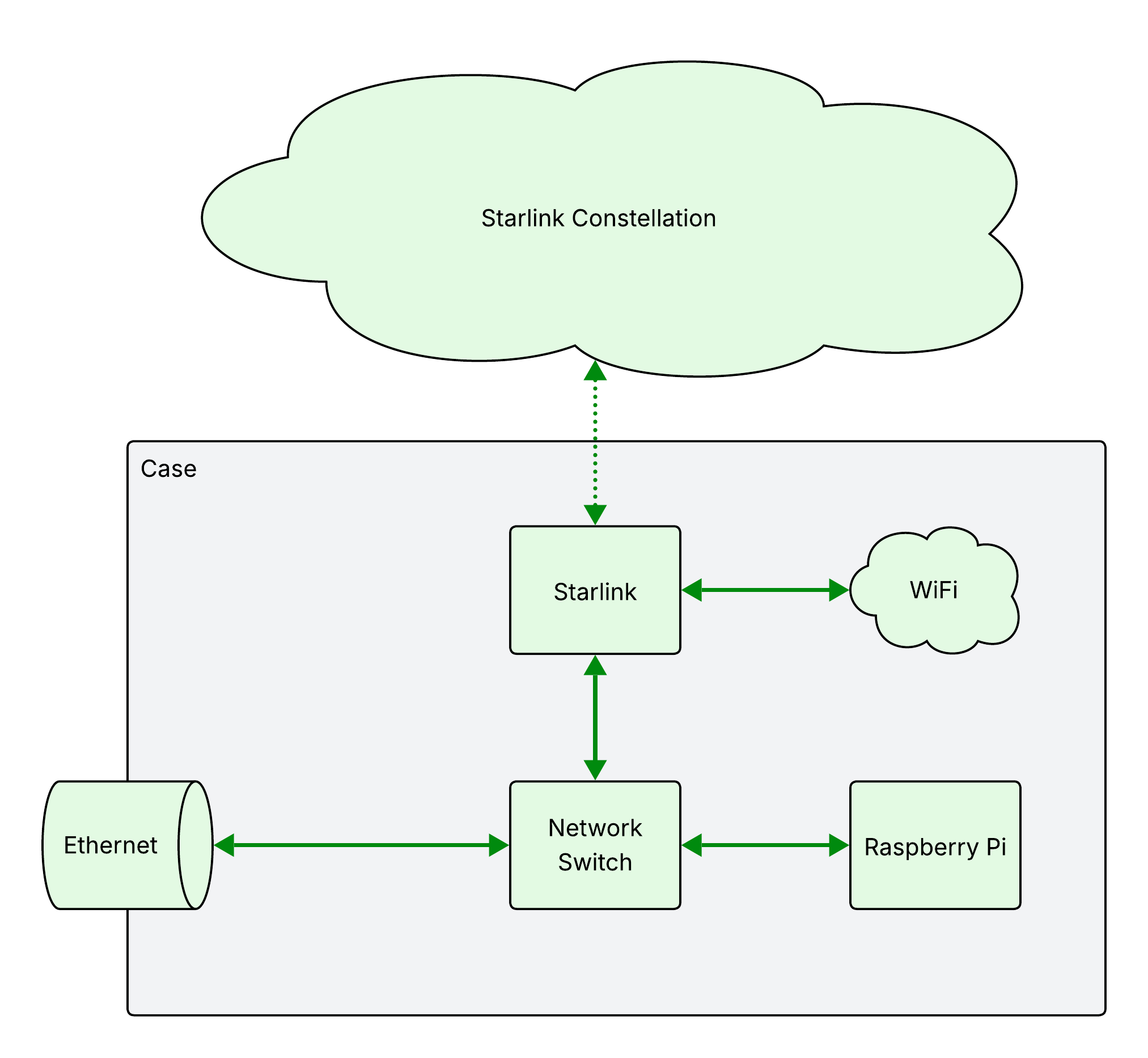
Starlink creates a WiFi hotspot, and connects via Ethernet to the network switch. The switch then connects to the Raspberry Pi and the water-resistant external ethernet jack.
Power
Campfyre receives its power from an internal battery and an external 12V supply.
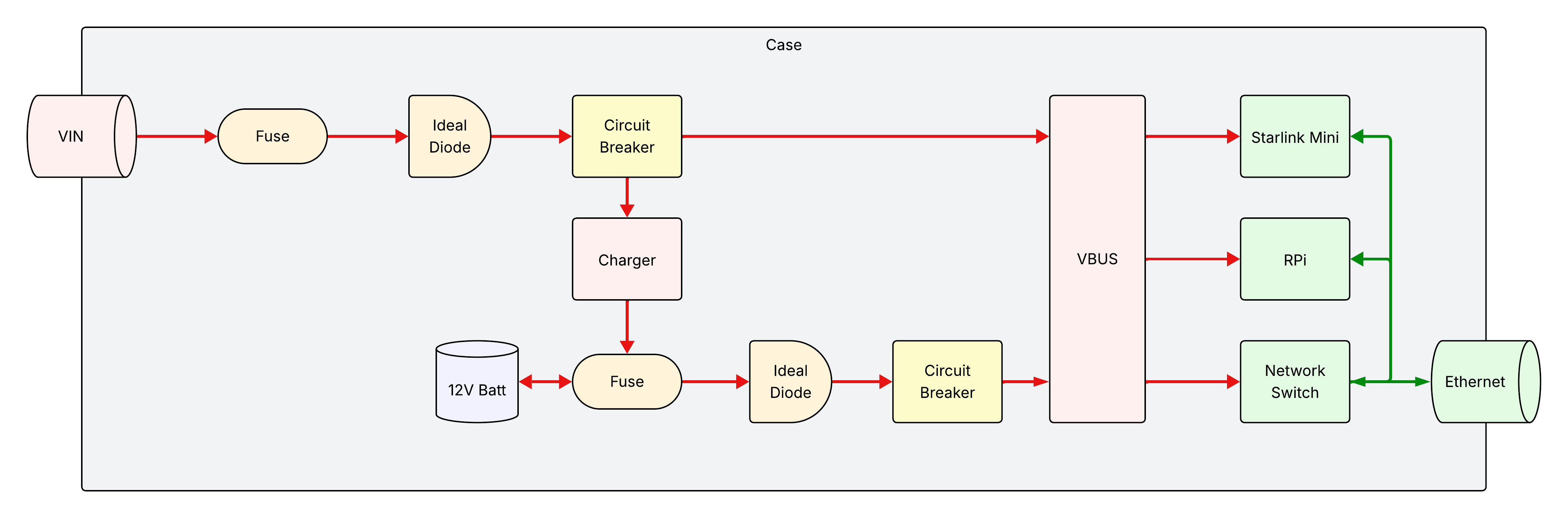
Components
- VIN
- Main connector for external DC power. It should be water-resistant and support the power requirements needed for Campfyre, as discussed in components.
- Ideal Diode
- This provides both reverse polarity protection externally, and prevents backfeeding of power from inside Campfyre to reach outside. In addition, this prevents VBUS from feeding back into the battery through the power path controller.
- Fuse
- This is to provide overcurrent protection, preventing a short circuit from causing fires.
- Circuit Breaker
- This is to turn on and off Campfyre internally, and provides additional protection against current spikes and short circuits.
- Charger
- The charger is for maintaining the internal battery. It needs to support DC in at the voltages provided by VIN, and should prevent the battery from being overcharged.
- 12V Battery
- The battery is a 4S LiFePO4 battery, which allows large numbers of charge/discharge cycles, and has a high capacity for its size. See its components page for more details.
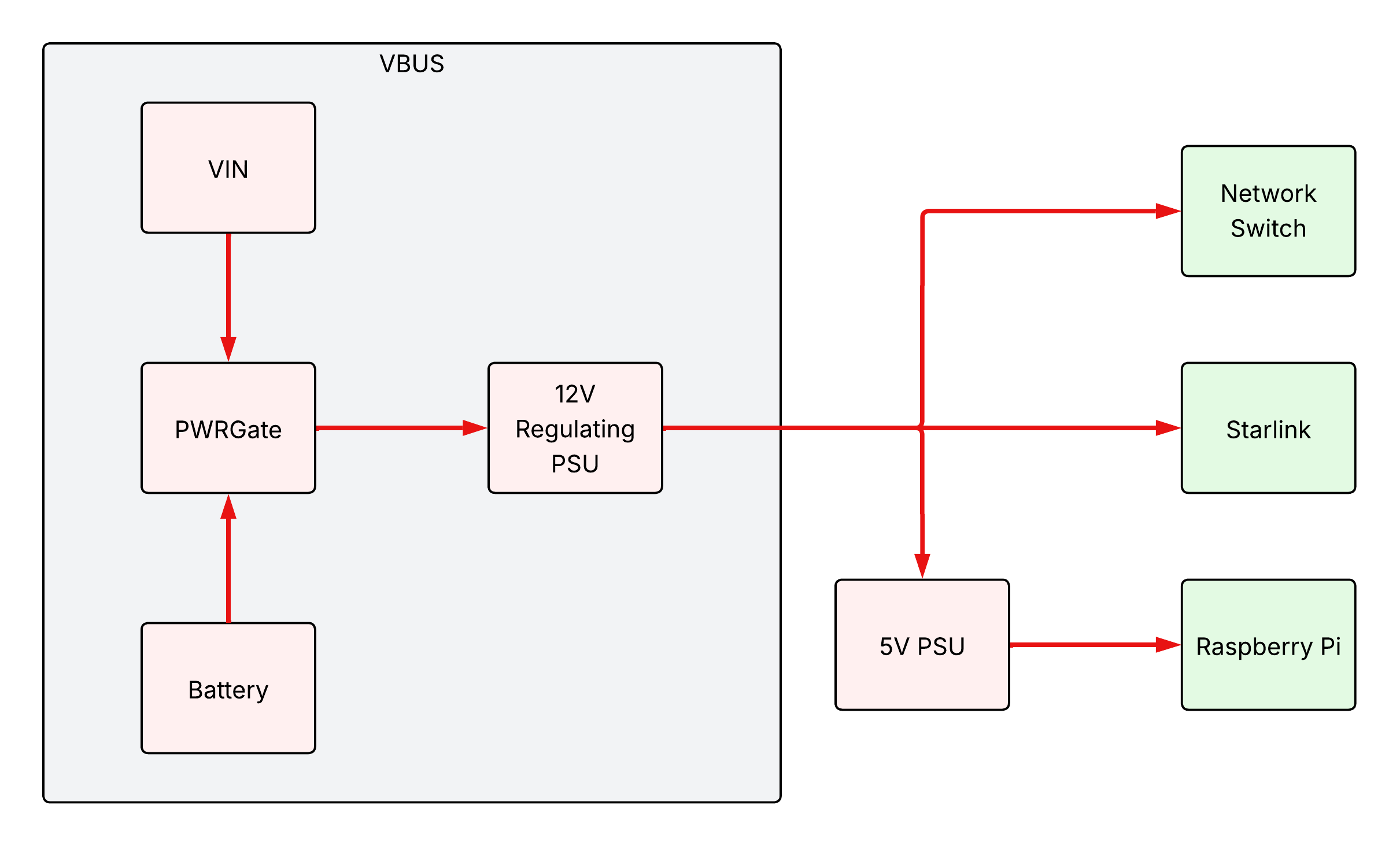
VBUS
VBUS is generated with a power path controller, switching automatically between the two input sources (VIN and the battery). See its components page for more details.
WARNING
Just because no circuit protection components are shown in the above diagram doesn’t mean they don’t exist! Make sure to properly install fuses, circuit breakers, and other components as detailed in the earlier power architecture diagram.
5 - Printable Parts
Parts to print for your Campfyre
These are all the parts you need to print to build your own Campfyre.
5.1 - Battery Holder
This is a predesigned holder for 150x65mm batteries. These are common LiFePO4 batteries found in uninterruptable power supplies, and can be ordered from the supplier listed in the components page.
5.2 - DCDC-8A Mount
The DCDC-8A Mount is the mount that holds the DCDC-8A in the case, allowing for it to be removed by unscrewing it rather than having it permanently affixed directly into the case.
5.3 - Epic PWRGate Mount
The Epic PWRGate is the power path controller which selects the power source to use for supplying the rest of Campfyre.
5.4 - Starlink Mount Corner A
This is what screws into the Starlink Mount to hold the Starlink Mini in place. Print two of these for Campfyre.
5.5 - Starlink Mount Corner B
This is what screws into the Starlink Mount to hold the Starlink Mini in place. Print two of these for Campfyre.
5.6 - Starlink Mount Half
This is the base that attaches to the case, to which the Starlink is then attached. Print two of these for Campfyre.
5.7 - Voltmeter Mount
This attaches the voltmeter (and associated pushbutton) to the side of the case, so you can check the battery voltage.