Architecture
2 minute read
Campfyre is designed around a few key subsystems. Green arrows in the diagrams are for Ethernet, and red arrows are for power.
Network
The network of Campfyre is designed to be centralized around a ruggedized network switch, where a Starlink Mini, a Raspberry Pi, and the output jack are all connected.
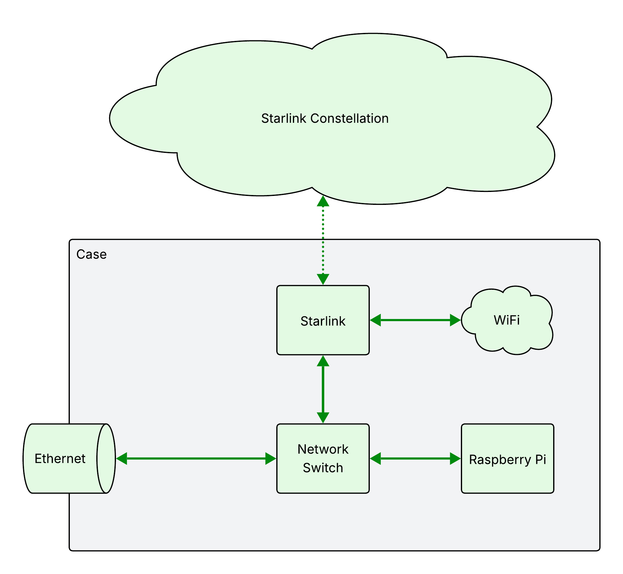
Starlink creates a WiFi hotspot, and connects via Ethernet to the network switch. The switch then connects to the Raspberry Pi and the water-resistant external ethernet jack.
Power
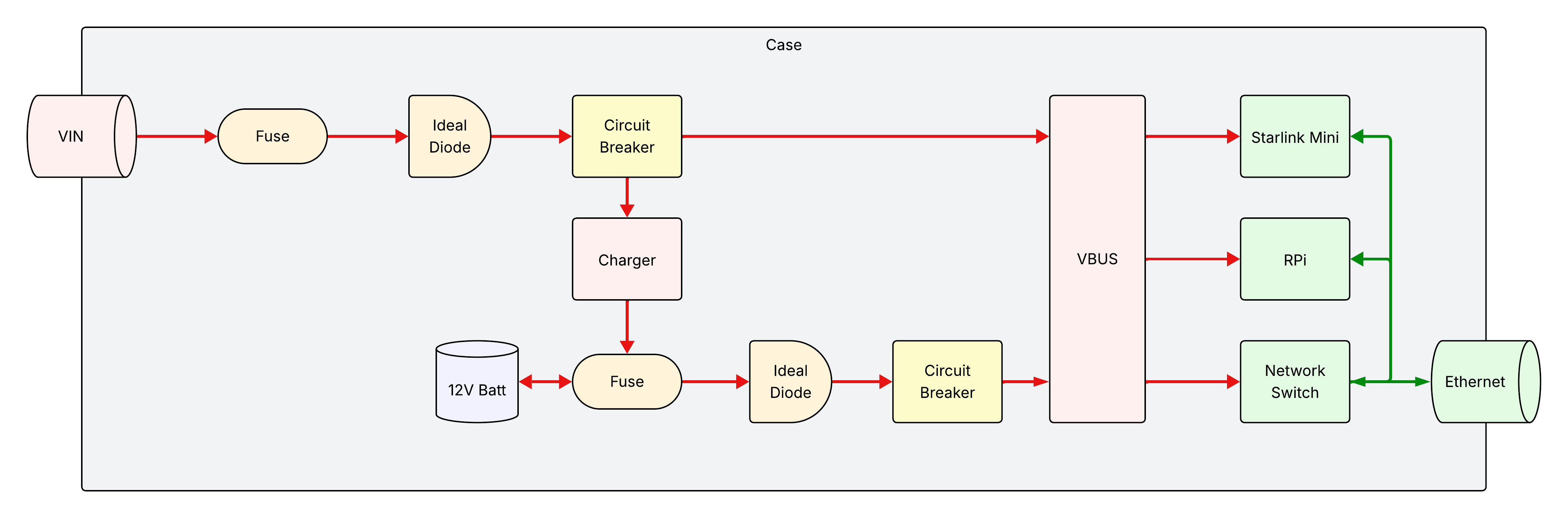
Campfyre receives its power from an internal battery and an external 12V supply.
Components
- VIN
- Main connector for external DC power. It should be water-resistant and support the power requirements needed for Campfyre, as discussed in components.
- Ideal Diode
- This provides both reverse polarity protection externally, and prevents backfeeding of power from inside Campfyre to reach outside. In addition, this prevents VBUS from feeding back into the battery through the power path controller.
- Fuse
- This is to provide overcurrent protection, preventing a short circuit from causing fires.
- Circuit Breaker
- This is to turn on and off Campfyre internally, and provides additional protection against current spikes and short circuits.
- Charger
- The charger is for maintaining the internal battery. It needs to support DC in at the voltages provided by VIN, and should prevent the battery from being overcharged.
- 12V Battery
- The battery is a 4S LiFePO4 battery, which allows large numbers of charge/discharge cycles, and has a high capacity for its size. See its components page for more details.
VBUS
VBUS is generated with a power path controller, switching automatically between the two input sources (VIN and the battery). See its components page for more details.
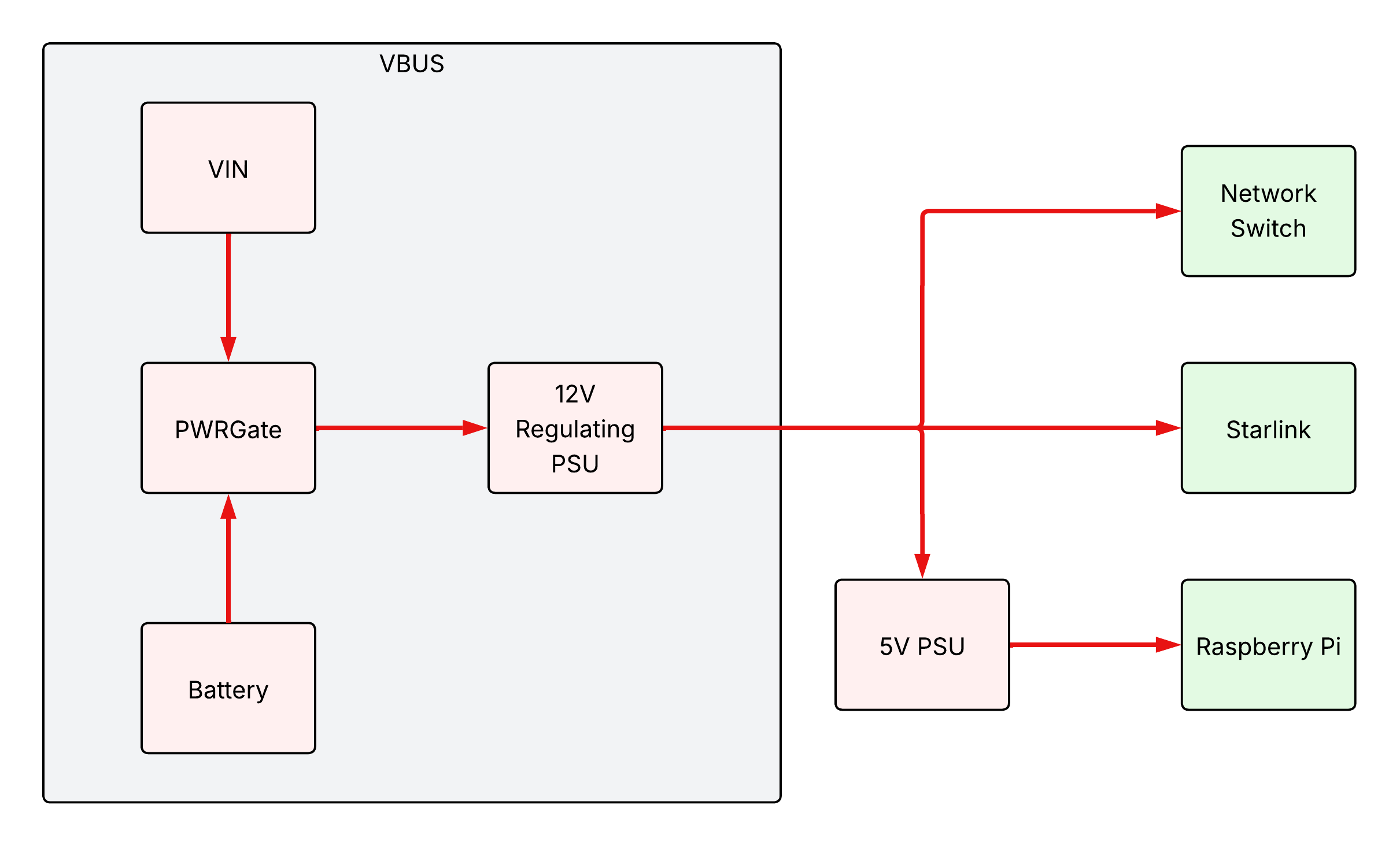
Just because no circuit protection components are shown in the above diagram doesn’t mean they don’t exist! Make sure to properly install fuses, circuit breakers, and other components as detailed in the earlier power architecture diagram.
Feedback
Was this page helpful?
Glad to hear it! Please tell us how we can improve.
Sorry to hear that. Please tell us how we can improve.